

There is a move away from using 2D drawings to communicate designs for manufacturing in many supply chains. 3D CAD models, with 3D annotations for product manufacturing information, is often used as the sole authority for manufacturing parts. This activity, referred to as model-based definition (MBD), hopes to eliminate errors that can result from misinterpretation or undocumented revision of part drawings. These 3D models are routinely translated from the format of the original design software into specialized design and manufacturing software programs that perform a specific function within the manufacturing process, such as fixture design, CNC operations, data translation, and inspection.
Unfortunately, the possibility does exist for data translations to introduce unintended changes to the model. If left undetected, these changes can cause costly errors in downstream manufacturing processes or worse yet, undetected changes in the design of parts that are put into service can have catastrophic consequences. Aerospace manufacturers recognized this issue and implemented quality standards that require any translated CAD data to be validated against a designated authority data set. By validating translated data, a second set of eyes is put on the translation process in an effort to catch any unintended change before it becomes a problem. The idea is always to “trust but verify” translated data. While this is primarily an activity that takes place within the aerospace supply chain at this point, other industries could certainly reduce the risk of downstream manufacturing errors due to unintended design changes by implementing a process for insuring the accuracy of translated design data.
What validation does is provide traceability to the original intended design. Therefore, whenever the authority model is used in a CAD/CAM/CAE software package other than the native design package, the translation of the authority data must be validated. Here are two specific application scenarios that have proven to be the most common within the aerospace supply chain.
As mentioned, validation of translation is performed to comply with quality standards to identify changes caused by the translation process. A comparison between the original authority data set and any derivative (translated) data sets ensures data integrity is maintained during the translation. The same could be said for any large-scale data migration process where authority data sets are batch translated into other file formats for use within the supply chain or for archiving of data.
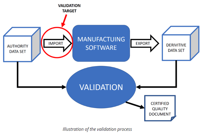
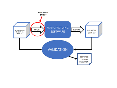
The process has proven to be extremely effective and has been adopted by many aerospace manufacturers. The authority data is read into the target manufacturing software, after which all of the part data is exported to any CAD format that will effectively support it. Clearly, manufacturing software packages must have at least one, high quality, industry standard or neutral file exporter for this method to be effective. Limited import and export capability of the software(s) in use can greatly inhibit this process. The exported data is called the copy (or derivative) file. The copy file is then validated to the authority file.
Two types of comparisons are used for validation, the first is a geometric comparison where like geometric entities (surfaces, solids, curves, points) are compared. This is the original application that most validation tools were developed to satisfy. In this situation, the validation tool is used to compare the contents of two files. A direct geometry to geometry comparison using a specified tolerance is performed to validate the translation.
The second type of comparison that can be used is a comparison of the original authority data set entities to a derivative set of points. This method is used when the receiving manufacturing software cannot successfully export all the necessary entity types to a suitable file format or when the current data flow can be left relatively unchanged by using a point derivative file for validation. A common use of this type of validation happens when inspection equipment (CMM with inspection software) is in use within the manufacturing process. If the authority model is used to define inspection parameters within the inspection software, the inspection software must be validated. The model is opened in the inspection software and used to define the nominal positions for inspection points. The nominal points are then saved in a neutral file format (IGES, STEP, CSV) and compared to the authority CAD model. The comparison provides the necessary traceability to the authority data. Comparison of derivative points to the authority data is an acceptable method of validation and is used as the sole comparison method in many validation tools. A problem with this method is that the “completeness” of the comparison is directly related to the density of the derivative point data. A more complete comparison is accomplished using the direct geometry to geometry method mentioned earlier. Kubotek has developed and uses a proprietary pattern matching algorithm that executes a complete geometric comparison of the authority and derivative data sets.
Quality System Standards and a New Paradigm
Communicating designs throughout the supply chain is critical to the success of any manufacturer, which is why aerospace manufacturers have put into effect strict standards for ensuring that translated data is traceable back to the manufacturer’s authority CAD model. Boeing, in particular, uses its’ D6-51991 Quality Assurance Standard, which requires that Boeing suppliers maintain the integrity of digital product definition data throughout all manufacturing operations. This type of data integrity requirement is meant to improve the design-to-manufacture process and supply chain quality and accountability. The new paradigm for achieving this success is model based definition where the CAD model is the sole authority for representing designs for manufacture. The drawing is being replaced as the authority for manufacturing parts.
In 2008, Kubotek lead the way for developing a tool that would satisfy the D651991 requirements for validation of translated data. As a long-standing leader in dealing with non-parametric, non-history based CAD models, Kubotek’s technology can mine intelligence from pure geometry (dumb models) and very accurately match geometric patterns. The technology has been developed for years to support CAD tools, and was effectively repurposed for model validation.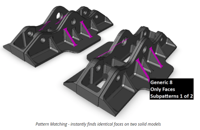
Potential Difficulties for Effective Validation Procedures
For effective validation of translations using current methods, the data export capability of the target software packages requiring validation must be seriously considered. There are times when an alternate translation workflow must be considered in order to assure that the validation process can be supported properly. While the goal is always to implement a validation strategy that requires minimal alteration of the current data workflow, there are times where more significant changes are unavoidable. Two things that can derail a process for validating translated data are poor export quality and the inability of the receiving software to export the required geometric entity types for validation.
Application Example: Poor export data quality and finding alternative workflows
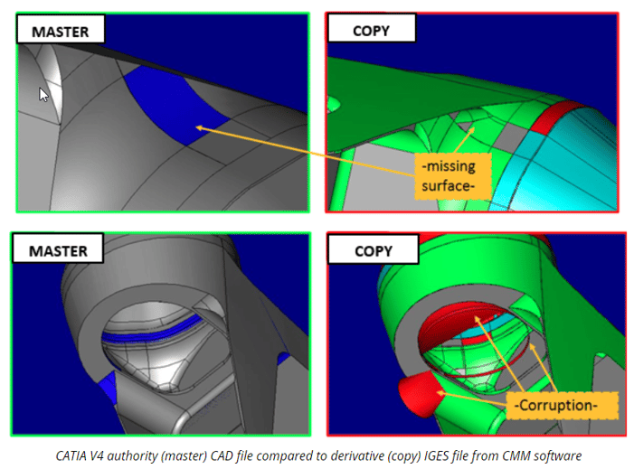
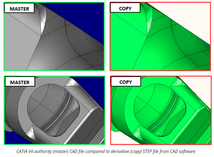
In this example, a Catia V4 (.model) authority file was read into a CAM/Inspection software program and exported via IGES. Afterward, the two files were compared for validation. Note that, in this example, the IGES file format was the only export choice available to “close the loop” for the validation. The exported files showed many areas where model quality was in question. Missing and corrupt surfaces existed throughout the model. In all figures below, the authority (.model) file is shown on the left.
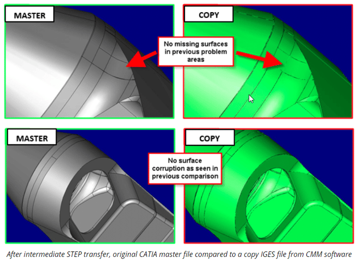
In the next step for comparison, the authority (.model) file was read into CAD software and exported using the STEP (.stp) file format. The results show a dramatic difference. No corrupt or missing surfaces were found and the files validated without differences. This would suggest that the CAD software does a better job of exporting this particular authority model than the CAM/Inspection software. The near perfect translation is shown below.
Let’s continue with this example by illustrating another interesting comparison that can be made while using the following workflow: Authority file> CAD>STEP>CAM/INSP>IGES. In this case, both the CAD software and the CAM/Inspection software are used within the validation workflow. This eliminates the read of the authority file (.model) into the CAM/Inspection software. The final IGES output file of this workflow is therefore validated to the authority file. The results of this comparison again show a dramatic realization of both the import and export capability of the CAM/Inspection software. The validation revealed no corrupt or missing surfaces in the final IGES output file. By converting the authority file (.model) using a high tolerance neutral file format (STEP) and a CAD software package, the data was more accurately read and therefore more accurately exported for validation purposes by the CAM/Inspection software (see figures below).
The use of an effective strategy for validating translations should always be considered. It is often the case that alternate translation workflows and validation procedures must be implemented to insure accurate and effective validation. The use of manufacturing software with adequate export capability to support the validation process; and investigating and planning a data translation/validation workflow that yields the highest quality data possible is essential. When possible, the workflow should easily fit within a standard validation process, and not disrupt the current manufacturing procedures or workflows.
Overall, validating data leads to better traceability, and ultimately, uniformity. In general, translated data should be trusted but verified to eliminate the risk associated with unintended changes. If changes occur as the authority data flows through the manufacturing process, they can be identified and traced back to the original error. This increases overall quality by eliminating mistakes prior to manufacturing. If the validation process finds a single mistake the cost savings could be substantial and in some cases huge scale rework of parts and manufacturing processes can be avoided completely. Translation validation could be a valuable tool to virtually any manufacturing supply chain where processes require the use of multiple data file formats.
Andy Beaupre is the General Manager of Sales and Support for Kubotek3D.
- Share
-

